Different types of input and output are combined depending on the requirements of the application.

Types of input and output

MAPAL uses five different types of input to link actuating tools and the machine tool. In addition to the machine type (machining center or special machine), the decisive factor is whether the machine used has a control function or not.

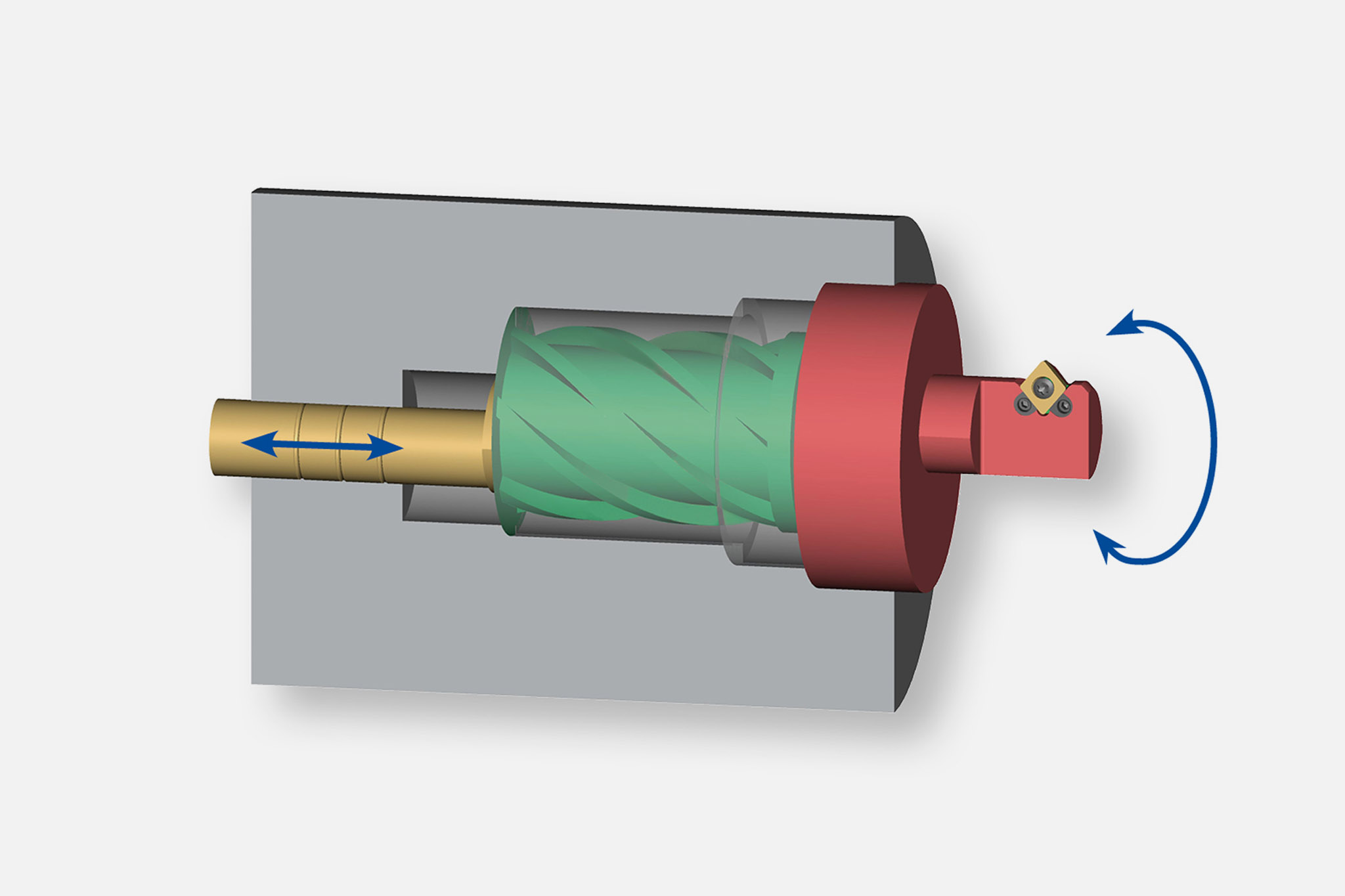
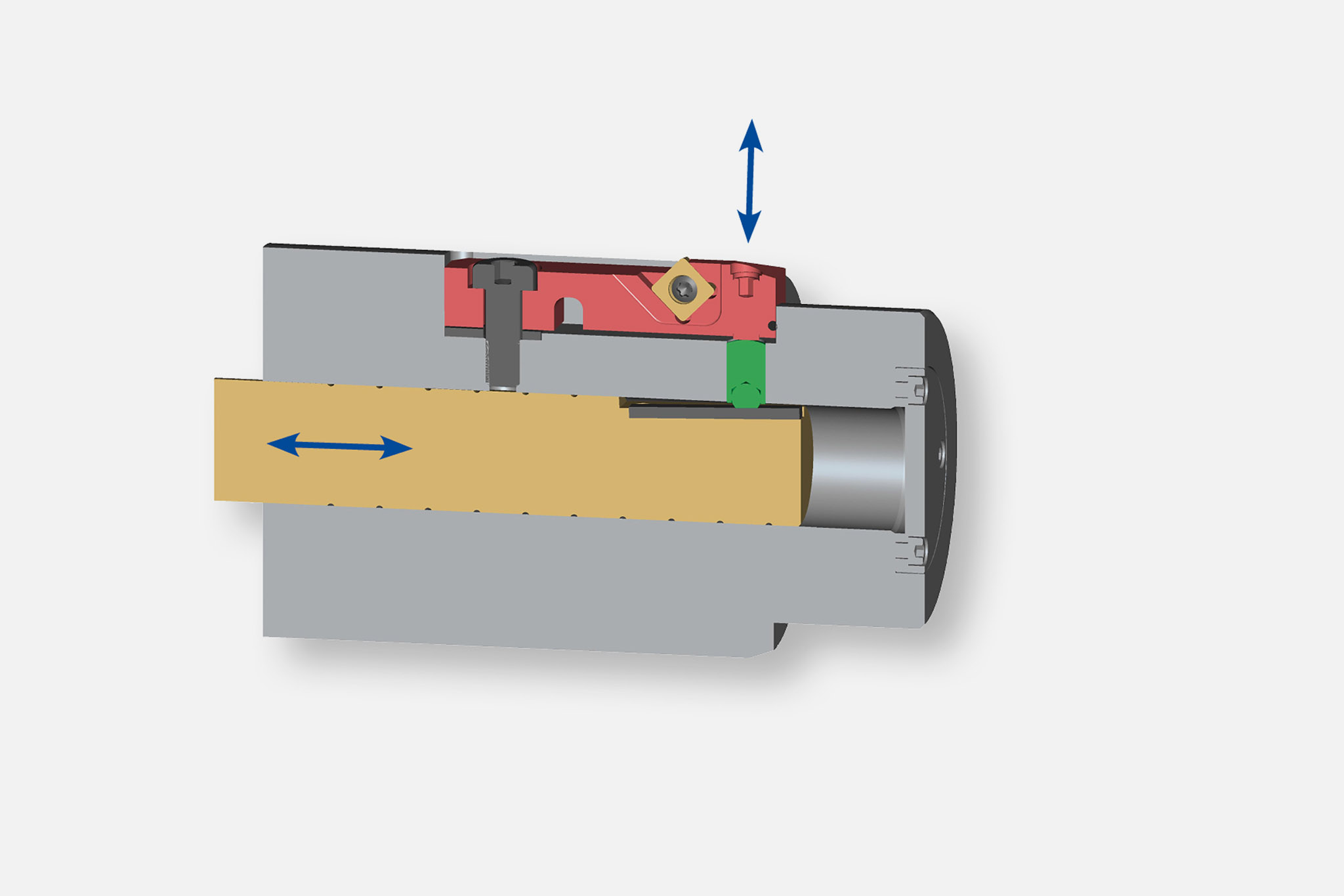
Six types of output are divided into the areas of 'moving and controlling' as well as 'compensating and lifting'.

A wide range of possible combinations result from these types of input and output. The most suitable combination is selected in close coordination between the MAPAL product specialists and the customer.

Types of input in detail

  • An actuation tool from MAPAL that uses coolant pressure as drive type.

    Input by means of coolant pressure

    The coolant pressure regulates the actuation of the slide or the positioning of the inserts.
    The feed rate is set manually via a regulator valve. Slides or inserts are returned via an internal spring.

    Tools actuated by coolant pressure can be used in machining centres without actuating function due to their variable connection.

  • An actuating tool from MAPAL with input by means of contact stop.

    Input by means of contact stop principle

    With this principle the contact stop socket comes into contact with the fixture or the workpiece. As a consequence the tool adapter is pressed into the tool and the slide actuated. The feed rate is defined by the machine axis. The slide is retracted by an internal spring. 

    Tools actuated by contact stop can be used in machining centres without actuating function due to their variable connection.

  • In this case, the TOOLTRONIC U axis is used as type of input for actuating tools.

    Input by means of TOOLTRONIC U axis / U axis spindle integration

    As a self-contained drive module, TOOLTRONIC represents a fully-fledged NC axis integrated into the machine control system that makes possible a wide range of applications using inductive energy and bidirectional data transmission.
    The slide is actuated by an actuating motor in the tool. 

    As a general rule, actuating tools that were activated in the past by coolant pressure, the contact stop principle or using a drawbar, can be driven and controlled both on machining centres and special machines without actuating function with TOOLTRONIC.

  • An actuating tool from MAPAL for use on machines with U axis systems.

    Input by means of the machine's U axis

    The slide is actuated via the U axis on the machine tool. The feed rate is set via the U axis. As a rule this axis is rotary and a fully functional NC axis.

    Wherever machining centres are equipped with U axis systems, suitably prepared controllable tools can be used.

  • A MAPAL actuating tool that is driven by the pull/push rod.

    Input by means of drawbar/push rod

    In a special machine, the central drawbar/push rod can be used for actuating the slide or positioning the inserts. 
    The feed rate is set via the U axis. This axis also provides the retraction (NC-controlled).

Types of output in detail

  • Schematische Darstellung eines Linearschieberantriebs von MAPAL Aussteuerwerkzeugen.

    Linearschieber

    Über eine Schrägverzahnung auf der Zug-/Druckstange wird der Linearschieber, der rechtwinklig zur Mittelachse des Werkzeugs steht, ausgesteuert.

    Bearbeitungen:
    • Einstechen
    • Konturdrehen
    • Plandrehen
    • ​​​​​​​Passlagerdrehen

  • Schematische Darstellung eines Schrägschieberantriebs von MAPAL Aussteuerwerkzeugen.

    Schrägschieber

    Der Schrägschieber steht ungleich 90° zur Mittelachse des Werkzeugs und wird über eine Schrägverzahnung auf der Zug-/Druckstange ausgesteuert.

    Typische Bearbeitungen mit Schrägschiebern:
    • Einstechen
    • Fasen
    • ​​​​​​​Kegeldrehen

  • Schematische Darstellung eines Schwenkschieberantriebs von MAPAL Aussteuerwerkzeugen.

    Schwenkschieber

    Ein interner Hebelmechanismus steuert den Schwenkschieber über einen zentralen Bolzen an. Die Eigenrotation des Werkzeuges und die überlagerte Rotation des Schwenkschiebers stellen einen Kugelabschnitt drehtechnisch her.

    Bearbeitungen:
    • ​​​​​​​Kugelkalotte drehen

  • Schematische Darstellung eines Drehschieberantriebs von MAPAL Aussteuerwerkzeugen.

    Drehschieber

    Das Aussteuern des Drehschiebers erfolgt über eine Kombination aus Drallwelle und Drallbuchse. Dabei wird die Axialbewegung der Drallwelle mittels Drallbuchse in eine Drehung / Rotation ungewandelt. Der Radialhub erfolgt durch exzentrische Lagerung. 

    Typische Bearbeitungen:
    • Einstechen
    • Konturdrehen
    • Plandrehen
    • ​​​​​​​Passlagerdrehen

  • Auch sogenannte Biege- oder Wipphalter kommen als Abtriebsart bei MAPAL Aussteuerwerkzeugen zum Einsatz.

    Biege- und Wipphalter

    Eine schiefe Ebene auf der Zug-/Druckstange ist beim Biege- und Wipphalter für das Aussteuern des Kurzklemmhalters verantwortlich. Je nach Lage der Zug-/Druckstange wird der Halter auf den entsprechenden Fliehkreisdurchmesser gestellt. 

    Bearbeitungen:
    • Schneidenverschleißkompensation
    • Drehen von kleinen Konturen
    • Einstechen